 |
| Jeremys SPI diagram |
Wikipedia says this about SPI:
"...SPI bus is a synchronous serial data link...that operates in full duplex mode. It is used for short distance, single master communication, for example in embedded systems, sensors, and SD cards. Devices communicate in master/slave mode where the master device initiates the data frame. Multiple slave devices are allowed with individual slave select lines. Sometimes SPI is called a four-wire serial bus, contrasting with three-, two-, and one-wire serial buses. SPI is often referred to as SSI (Synchronous Serial Interface)."During the #8 video exercise, you will build a program using SPI, doing things like including the SPI library, setting the slave select pins, and sending information on the SPI bus with the SPI.transfer command. Going through this exercise doesnt make you an SPI expert, but it does help you learn a few basic aspects of SPI. For a more thorough background on this topic, take the time to go through the SparkFun tutorial on SPI.
 |
| AD5204BN10 digital potentiometer |
In the meantime, I did a bit of research on digital potentiometers so Id understand a little more about how they work and when to use them. Analog Devices has a tutorial on digipots, and since they made the one that Jeremy uses in the video, I decided the AD tutorial was a good place to start. Nine pages later I decided I was wrong. The AD tutorial was written for an electrical engineer, not a novice electronics person. Electronic Design (ED) had a much better newbie introduction to digipots. ED said:
 |
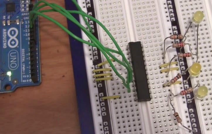
| Breadboard setup for #8 video exercise |
"Digital potentiometers are integrated circuits that implement a resistive ladder and a digital means of addressing a particular tap on the ladder that corresponds to the wiper position of a mechanical potentiometer. They’re used to calibrate system tolerances or dynamically control system parameters. Some of them have no on-chip memory. Others incorporate nonvolatile memory for saving the wiper position...What advantages do digital potentiometers have over mechanical pots? Obviously, digital pots can be operated in a closed control loop, and they don’t require physical access for adjustment. In addition, they offer higher resolution than mechanical pots, along with better reliability and stability, faster adjustment, better dynamic control, and a smaller footprint."Jeremys use for the digital potentiometer in the #8 video exercise is to vary the input voltage to LEDs to change their brightness. I dont know if thats a typical application for a digital potentiometer, but its a good way to learn about this component.
If youre interested in microcontrollers, please come to the Humboldt Microcontrollers Group meeting this Thursday, July 24, from 6 to 8 PM at 1385 8th Street, Arcata, California, USA. Bring your questions and your enthusiasm -- we look forward to seeing you there!
**********